- 您现在的位置:买卖IC网 > Sheet目录1242 > SFPA32GBQ1BO8TO-I-QT-223-STD (Swissbit NA Inc)FLASH SSD SMART UDMA 2.5" 32GB
�� �
�
�6.3� Ultra� DMA� Mode�
�6.3.1� Ultra� DMA� Overview�
�Ultra� DMA� is� an� optional� data� transfer� protocol� used� with� the� READ� DMA,� and� WRITE� DMA,� commands.� When�
�this� protocol� is� enabled,� the� Ultra� DMA� protocol� shall� be� used� instead� of� the� Multiword� DMA� protocol� when�
�these� commands� are� issued� by� the� host.� This� protocol� applies� to� the� Ultra� DMA� data� burst� only.� When� this�
�protocol� is� used� there� are� no� changes� to� other� elements� of� the� ATA� protocol� (e.g.,� Command� Block� Register�
�access).�
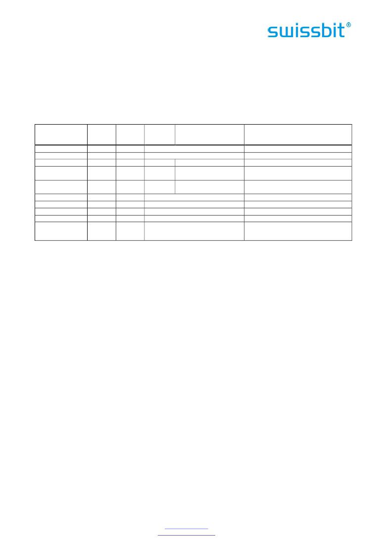
�The� usage� of� signals� in� each� of� the� modes� is� shown� in� Table� 21:� Signal� Usage� in� PIO/MDMA� vs.� UDMA� Mode�
�Table� 21:� Signal� Usage� in� PIO/MDMA� vs.� UDMA� Mode�
�UDMA� Signal�
�Pin�
�Type�
�PIO� /�
�UDMA�
�Remark�
�MDMA�
�DMARQ�
�DMACK�
�21�
�29�
�Output�
�Input�
�DMARQ�
�-DMACK�
�STOP�
�23�
�Input�
�-IOWR�
�STOP�
�1�
�-HDMARDY(R)�
�HSTROBE(W)�
�-DDMARDY(W)�
�DSTROBE(R)�
�HDMARDY(R)�
�HSTROBE(W)�
�DDMARDY(W)�
�DSTROBE(R)�
�DATA�
�ADDRESS�
�CSEL�
�INTRQ�
�Card� Select�
�25�
�27�
�3� -� 18�
�33, 35, 36�
�28�
�31�
�37,� 38�
�Input�
�Output�
�Bidir�
�Input�
�Input�
�Output�
�Input�
�-IORD�
�IORDY�
�D[15:00]�
�A[02:00]�
�-CSEL�
�INTRQ�
�-CS0,� -CS1�
�1,� 2�
�1,� 3,� 4�
�1,� 3�
�1.� 2.� 4�
�UDMA� write� clock� from� host�
�UDMA� read� clock� from� drive�
�Notes:�
�1.�
�2.�
�The� UDMA� interpretation� of� this� signal� is� valid� only� during� an� Ultra� DMA� data� burst.�
�The� UDMA� interpretation� of� this� signal� is� valid� only� during� and� Ultra� DMA� data� burst� during� a� DMA�
�Read� command.�
�3.� The� UDMA� interpretation� of� this� signal� is� valid� only� during� an� Ultra� DMA� data� burst� during� a� DMA�
�Write� command.�
�4.� The� HSTROBE� and� DSTROBE� signals� are� active� on� both� the� rising� and� the� falling� edge.�
�Several� signal� lines� are� redefined� to� provide� different� functions� during� an� Ultra� DMA� burst.� These� lines�
�assume� these� definitions� when:�
�1.�
�2.�
�an� Ultra� DMA� mode� is� selected,� and�
�a� host� issues� a� READ� DMA,� or� a� WRITE� DMA� command� requiring� data� transfer,� and�
�3.� the� device� asserts� (-)DMARQ,� and�
�4.� the� host� asserts� -DMACK.�
�These� signal� lines� revert� back� to� the� definitions� used� for� non-Ultra� DMA� transfers� upon� the� negation� of� -�
�DMACK� by� the� host� at� the� termination� of� an� Ultra� DMA� burst.�
�With� the� Ultra� DMA� protocol,� the� STROBE� signal� that� latches� data� from� D[15:00]� is� generated� by� the� same�
�agent� (either� host� or� device)� that� drives� the� data� onto� the� bus.� Ownership� of� D[15:00]� and� this� data� strobe�
�signal� are� given� either� to� the� device� during� an� Ultra� DMA� data-in� burst� or� to� the� host� for� an� Ultra� DMA� data-�
�out� burst.�
�During� an� Ultra� DMA� burst� a� sender� shall� always� drive� data� onto� the� bus,� and,� after� a� sufficient� time� to�
�allow� for� propagation� delay,� cable� settling,� and� setup� time,� the� sender� shall� generate� a� STROBE� edge� to�
�latch� the� data.� Both� edges� of� STROBE� are� used� for� data� transfers� so� that� the� frequency� of� STROBE� is� limited� to�
�the� same� frequency� as� the� data.�
�Words� in� the� IDENTIFY� DEVICE� data� indicate� support� of� the� Ultra� DMA� feature� and� the� Ultra� DMA� modes� the�
�device� is� capable� of� supporting.� The� Set� transfer� mode� subcommand� in� the� SET� FEATURES� command� shall� be�
�used� by� a� host� to� select� the� Ultra� DMA� mode� at� which� the� system� operates.� The� Ultra� DMA� mode� selected� by�
�a� host� shall� be� less� than� or� equal� to� the� fastest� mode� of� which� the� device� is� capable.� Only� one� Ultra� DMA�
�mode� shall� be� selected� at� any� given� time.� All� timing� requirements� for� a� selected� Ultra� DMA� mode� shall� be�
�satisfied.� Devices� supporting� any� Ultra� DMA� mode� shall� also� support� all� slower� Ultra� DMA� modes.�
�An� Ultra� DMA� capable� device� shall� retain� the� previously� selected� Ultra� DMA� mode� after� executing� a� software�
�reset� sequence� or� the� sequence� caused� by� receipt� of� a� DEVICE� RESET� command� if� a� SET� FEATURES� disable�
�reverting� to� defaults� command� has� been� issued.� The� device� may� revert� to� a� Multiword� DMA� mode� if� a� SET�
�FEATURES� enable� reverting� to� default� has� been� issued.� An� Ultra� DMA� capable� device� shall� clear� any�
�Swissbit� AG�
�Industriestrasse� 4�
�Swissbit� reserves� the� right� to� change� products� or� specifications� without� notice.�
�Revision:� 1.00�
�CH-9552� Bronschhofen�
�Switzerland�
�www.swissbit.com�
�industrial@swissbit.com�
�P-120_data_sheet_PA-QxBO_Rev100.doc�
�Page� 14� of� 76�
�发布紧急采购,3分钟左右您将得到回复。
相关PDF资料
SFPK-SL
CONN SFP CAGE
SFSA16GBV1BR4TO-I-QT-226-STD
FLASH SLC UDMA/MDMA/PIO 16GB
SFSA32GBQ1BR8TO-I-QT-226-STD
FLASH SLC UDMA/MDMA/PIO 32GB
SFSA32GBU1BR4TO-I-NC-216-STD
FLASH X-200M SLC MSATA 32GB
SFSA32GBV1BR4TO-I-NC-216-STD
FLASH X-200S SLC SLIM SATA 32GB
SFSA64GBQ1BR8TO-I-NC-216-STD
FLASH SSD UDMA IND 2.5" 64GB
SFSO4404NR
FEMALE SCREWLOCK 4-40 .197"
SFW22R-1STE1
SFW22R-1STE1-FFC/FPC CONN
相关代理商/技术参数
SFPA32GBQ1BO8TO-I-QT-243-STD
制造商:SWISSBIT NA INC 功能描述:FLASH
SFPA36AT0250
制造商:General Electric Company 功能描述:SFP 3P 600V 250A
SFPA4096Q1BO2TO-C-DT-243-STD
制造商:SWISSBIT NA INC 功能描述:FLASH
SFPA4096Q1BO2TO-I-DT-223-STD
功能描述:FLASH SSD SMART UDMA 2.5" 4GB RoHS:是 类别:计算机,办公室 - 元件,配件 >> 固态硬盘驱动器 系列:P-120 标准包装:1 系列:- 存储容量:64GB 存储器类型:闪存 - NAND 其它名称:VL 64 GB SSHD KITVL64GBSSHDKIT
SFPA4096Q1BO2TO-I-DT-243-STD
制造商:SWISSBIT NA INC 功能描述:FLASH
SFPA-53
制造商:未知厂家 制造商全称:未知厂家 功能描述:Schottky Barrier Diodes
SFPA-63
制造商:SANKEN 制造商全称:Sanken electric 功能描述:Schottky Barrier Diodes (Surface Mount) 30V
SFPA-73
制造商:未知厂家 制造商全称:未知厂家 功能描述:Schottky Barrier Diodes